Tuesday 9 September 2014

Table saw build part 3.

At the weekend, I continued with the saw. I used a die wrench to cut the M20 thread in the driveshaft. Again, a learning experience. I'd really forgotten how to cut threads (if I even ever knew). The trick is to turn the wrench until it's tight, and then wind it back, clean out the swarf and repeat. Do not try to cut lots of thread in one go. I ended up doing about a 1/8th turn each time. It took a while. I did have a look at the lathe to see about cutting the thread in that. I can't see how to select a metric thread, which is a pain. It could be that it doesn't have the metric gearbox. I'll have to investigate further. Given the bar is 20mm, cutting a metric M20 thread makes the most sense.

Once the thread was cut, it was time to see if the nut fits OK.


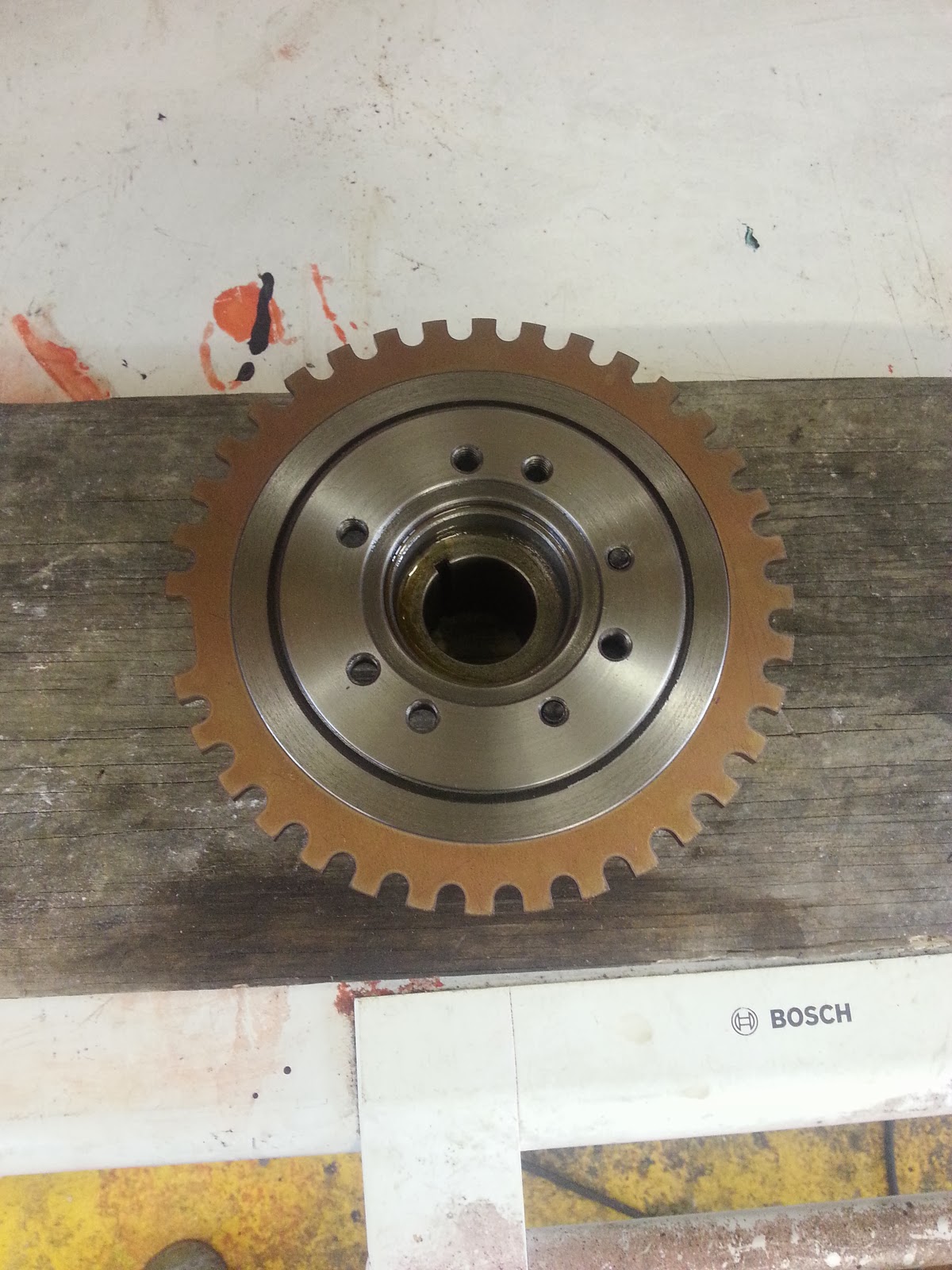
It's taking shape now - the brass piece is the clamp for the outside of the blade. The big nut will push against it. Like this:


Here's the other side:


Since I do admit my mistakes, that bit where the shaft is turned down slightly is where I clamped it in the vice for when I was using the die. I managed to get the vice to chew the shaft up a bit. I chucked it back up in the lathe to tidy it up.

As before, I now need to fit a pulley so that I can drive the shaft. My last attempt ended in disaster and a smashed pulley. This time I managed it. So again, first bore out the pulley:


Then, brass insert in the freezer, pulley on the Aga, and with the help of a big vice:


It's in!

I then bored that insert to 20mm to fit the shaft. I broke a drill doing it too. Didn't spin the insert fast enough I think. In the end though, it's on the shaft:


So now, apart from actually attaching the pulley and the blade to the shaft, that's that bit done!


Lots still to do. Plan is to build a sort of frame for the driveshaft and motor and so on. I'm not sure what to call this, I guess the 'saw unit'. Then attach that to the bottom of the table.

Now I can see what's what, I think the depth of cut should be just under 150mm.

Tuesday 2 September 2014

Table saw - couple of steps forward, one back!

I had another go at the table saw last weekend.

Now at least all the components for making the saw and the driveshaft had turned up, and so had a few more tools, so I was ready to crack on.

I'm making an arrangement to clamp the blade to the shaft. Basically, I'm turning a sleeve of brass, with a 30mm register that will hold the blade, bored to 20mm for the shaft. I'll bore into that at 90deg and tap it for a pair of grub screws. The clamp itself will be held against the blade by an M20 nut, which I'll have to cut a thread for on the shaft. I need to learn to cut threads on the lathe, but for now I'll just use a die and die wrench. Because I need to cut a thread, I can't hold the thread cut end in a pillow bearing, so I bought a 18.5mm pillow bearing and turned the driveshaft down to mate with it. The threaded part will be next to the turned down part.

Here are some pics to illustrate:


You can see that the bright steel  bar that is my driveshaft for the saw goes all the way through the headstock - a cool feature of the lathe. Here you can see that I've turned down the shaft.


I'm learning all the time. Doing this, I learnt that you need to spin bright steel fast to machine it. I broke my parting tool finding that out.

I fitted it to the pillow bearings just to see: 


The one nearest the camera is the small dia one (obviously!).

Next I wanted to make the pulley for the drive shaft. This is going to be a bit problematic because I don't have a keyway in the shaft, so I need to use a grub screw again. I'll need to make a dimple in the driveshaft for the grub screw to go into so that there's a positive lock, or the motor will just spin the pulley on the shaft (I think). Trouble is, you can't get a small pulley with a large diameter bore and  a grub screw. My plan is to bore out the pulley's centre, and then make an insert out of brass to an interference fit to the bored out pulley. Then bore out the insert to the diameter of the shaft.

So first, bore out the pulley:


The pulley started with a 15mm dia bore. First I bored it to 19.5mm, then to 29.5mm, then reamed it to 30mm.

All good so far.

Now make the insert:


Then put the insert in the freezer, and the pulley on the barbecue. Then pop the insert into the pulley, and away we go:


Oops. That wasn't supposed to happen.

I was a little annoyed at that point, so I wasn't so snap happy with the photos, but I started to make the saw blade clamp.


You can see that it's sitting on the lump of brass from the previous post, but now there's a register that's poking through the hole in the saw. The other side of the clamp is off to the left. It's slightly conical, because of the broken parting-off tool, I couldn't make a straight cut. Anyway, it looks fine like that.

Here's the assembly as a complete clamp:


There you go. Slow progress, but progress none the less. I've ordered a new pulley, so that should be the next thing. And a new parting off tool, so I can complete the clamp.

One thing I was surprised at was how poor the bearings are. They work OK, but 2 of the three bearings had the bearings pressed into the cases off-square, and of the two identical bearings, one has a shorter pedestal height than the other. I'll work around this, but although I didn't buy expensive ones, I didn't expect that at all.

Wednesday 27 August 2014

More table saw...

The table saw I want to build is fairly basic, and I want to be able to use it to cut fairly large pieces of timber. So I want a decent amount of saw blade sticking out from the table. Best way to start is with a big saw blade then.


You can also see that I have some pillow bearings, a lump of brass bar, and a rusty piece of angle iron in shot. The pillow bearings are because I want to run the saw on a shaft and not have it directly driven by the motor. This way, I don't have to get the table up and over the motor, which will maximise the amount of protruding saw blade, hopefully. The brass bar is to make a blade clamp. This will attach the blade at right angles to the drive shaft.The angle iron is for the fence. The fence on a table saw is the thing that regulates how much is cut off. So you set the fence where you want it (say 20mm from the blade), press your timber up against the fence and push it towards the blade. The strip between the blade and the fence will be 20mm.

Because I don't have the shaft and a couple of necessary other tools, I started on the fence.


I chopped the angle iron down to size. So far it's a 1500mm fence. Now I needed to make it onto runners. 

I had some linear bearings from a CNC machine project that I've yet to start, so I've robbed them:


They come on a track as you can see. The track is 1000mm long, so that's the order of the fence's travel (less dimensions of bearing carriage).

I wanted to use both bearings on each track (bit overkill probably), so I needed to join them together in a carriage arrangement. I had some aircraft grade aluminium alloy, so I used my Evolution chop saw to cut the carriage tops:


Then it was the painful process of marking and drilling in order to make the carriage. The required accuracy is high. If the bearings are not square to each other and to the rail, the carriage will have, at best, massive stiction. Or it won't run on the rail at all. This process was made harder because I didn't have a diagram showing the hole centres for the bearings, and I couldn't find one for the precise model of bearings I have. In any case, with a bit of jiggery pokery with a vernier caliper I made some progress, and used an optical centre punch to mark the holes:


Took a while to get all 8 holes drilled - probably about 20mins a hole when all said and done!


You can kind of see where this is going. The fence will glide on the bearings. Clearly I need to mount the bearings such that the fence is right on the saw table top, but we're moving in the right direction.


Some more stuff has arrived from the 'bay, so hopefully I'll be able to continue the project soon. I'll need to, as I'll need the saw with all the DIY I have going on in the new house!


More excuses, no progress on car or bike. Table Saw!!

Well the pressures of the kids are unrelenting, and so, to alleviate that, we decided we'd move house. This isn't done yet, but the house is old (probably Georgian, not that I'd know how to judge it), and hasn't changed hands in over 100 years. It looks like a few generations have had there time there, and now it really does need a bit of work. So given I know I'll be doing some serious work there, I thought that I'd build a table saw.

So I looked on YouTube. There's a variety on there, from the elaborate like this fellow:


And pt.2 (because it is a great effort)


To the more like 'get a hand held circular saw and turn it upside down' type efforts:


Nothing really took my fancy, so I've decided to go my own way a bit.


Monday 7 April 2014

New arrivals

I've had this rule about not just buying stuff and showing it off, preferring to wait until the bits are actually attached to something (this is the car, and more specifically the engine, in case you were wondering), but I'm so close to actually having everything I need to build the bottom end up completely that I can't resist.

Here's what arrived today:


Specifically the stuff in the foreground. From L to R, Flywheel (with distributor drive on top, plus clutch cover bolts and sump bolts, windage tray, sump and oil pickup.

What's that all for? Well, the flywheel is self explanatory, the distributor drive cog - I need that even though I'm not running a distributor to fire the ignition because the distributor drives the oil pump on these engines. The windage tray is to stop the crank whipping in the oil - keeps the oil in the sump away from the crank. The sump itself is extended at the sides and built into it is a set of trapdoors that allow the oil toward the pickup, but not away and the pickup itself sits in the middle of the well at the front of the sump and feeds the oil pump.

Also in the garage: 


You can't see it all here, but there's the crank, rods, pistons, clutch cover, clutch, pulley set, damper (with attached trigger wheel), high volume oil pump, bottom end girdle, camshaft, followers, roller conversion kit and high volume water pump.

I now have everything I need to get a full balance done. The only thing (apart from that work) that's stopping me building the bottom end is finding an early front cover so that I can have a dipstick for the oil.The early 302 front covers have a dipstick hole, the later blocks (like mine) have that hole in the side of the block. That side will be inaccessible on the TVR, and in any case, the dipstick wouldn't go in that front well in the sump. More to come....


Saturday 8 March 2014

Trigger Wheel Part 2

Well, it's on.

Pretty straightforward, even for a proper lathe beginner like me. It's feels good, though, to be a total novice, but still able to do something that's useful.

Here's the damper with the register cut in it:


It's sitting on the freezer in the garage. I popped it in there for a short while just to cool it down and get it to shrink a tiny bit.


I ended up buying two verniers after my cheap one let me down. They are identical, except one is  a 6" and one a 12. Hope these are better. They're made of stainless, so hopefully good enough.

I also put the trigger wheel itself on the hot ring of our Aga. It kind of changed colour a bit. Not sure why.


Anyway it did the trick - I didn't take a photo illustrating this, but with both the components at the same temp, they would not go together. But doing the heat one/cool the other thing worked a treat:


See what I mean about the colour change?


I've been thinking about how to test this out, and I guess I have the perfect thing - I can spin this in the lathe and mount the sensor in the cross slide somehow and actually get the ECU to output the rpm.

Not much else to report - although this one has left me feeling pretty happy.

I'm still contemplating drilling and tapping the damper, and using machine screws to pin the wheel to the damper. I'll think more on it this week.


Saturday 1 March 2014

Trigger wheel pt.1.

In the last post, I wrote that I needed to attach the trigger wheel to the crank somehow in order for it to be able to be used to fire the ignition system. The logical place to attach this to is the crankshaft damper. This is a big lump of nodular iron that is attached to the front of the crank with the aim of contributing to (1) the balance of the engine, (2) the flywheel effect and (3) damping the effects of the crank's turning the up-and-down motion of the pistons into rotational motion.

The 'easy' option is to bolt it to the front of the damper, but the problem here is that the bottom pulley attaches to the damper. That's OK, but anything the belts touch (alternator, water pump, power steering) would need spacing forward 5mm (the thickness of the steel of the trigger wheel), which is a pain. My solution to this is to turn a register in the damper and attach the trigger wheel that way. I am aiming for an interference fit, so I'll have to cut the register pretty accurately (within a thou or so) I think. I reckon to be having to put the damper in the freezer and the timing ring in the oven to get the two things to mate together.

Probably some of you are thinking about the consequences of attaching the timing wheel now on the timing. So basically the question is "how do you know where TDC on pot one is without the engine together?" Well, I don't. I could build the engine up and do this prior to balancing (and I may yet do), but with the software the Emerald ECU runs, you can supply an offset. So perhaps I position the timing wheel 90Deg from where it should be, I can correct this out in the software.

So, in terms of pics, here we are - the damper mounted in the four jaw on the lathe:


On the four jaw chuck, the jaws move independently of one another.This means you can set jobs up in the lathe with great accuracy. You can see the dial gauge mounted on the cross slide here. It took a while, but the damper spins in the chuck with less than 1 thou run out. That's pretty true.

Unfortunately my digital vernier let me down. It was a cheapie, and it was a bit old, so I got what I deserved - cheap tools always let you down when you want them. This meant I couldn't complete the cutting of the register because I can't measure with anything like enough accuracy how much to take off.

Here's the cut so far:


Lots to go. Here's a pic with the trigger wheel:


There's a slight risk in the way I'm doing this. That ring you can see outside the bolt holes on the crank damper is a ring of rubber that's bonded to either half of the damper. Obviously the wheel will be able to move fractionally. However, I'm betting that in real life, this makes sod all difference.

Got some more inspiration for the Enfield: http://vimeo.com/30586946. Cheers Jim.

Followers